Ooops i did it again... i fixed someone else's trash... for my kids only...
This dirty Moderno kids Jeep (500$ on Amazon) was found in front of a neighbor house the day before trash pick up ... under a pile of garden trash bags and with a dead mouse or mole in it. (RIP) I pressure washed it and bleached it. the fake leather seat took a few days to dry inverted in the sun.
First: find a battery, does it run on 6 or 12v?
-12v according to amazon. works using my old ridekick Pb batteries 12AH 12V SLA-AGM (hooked to a homemade 14 gauge copper wire with XT60 male connector and terminals and it connects in the bottom of the battery compartment nicely.) action run time ~45 min
The switch issue : (most likely why it was in a trash pile)
Power startup was erratic... the kids had to push it ~20 times before it would work each first few session... Ding! it s corroded.
getting it out the hard way... perhaps it would pop out of the dash with a screw driver too? next time...
The internal mechanism after cleaning...
If yours stops working: corrosion inside most likely. open, clean the contact and add WD40. Beware of the small clicking mechanism, hard to put back together right. also i d recommend placing a floppy piece of transparent tape (partly 2 sided so it does not stick to the switch only to the dash) on top of it on the dashboard to prevent/limit water getting in it.
Conclusion:
-The lights work
- The sound system almost works nicely with programmed music, USB, SDcard slot, bluetooth, ...only the FM radio does not work!
here is how i plan to put the kid bikes on to go to:
- the park with kids and little bikes
- from/to school (with backup kid carrier trailer if they get tired on the way)
HOW?
- Remove the wheel locking mechanism (we never use it anyways, only an annoyance when the kids lock it for "fun")
- The Burley trailer then has 2 free holes under the rear structural bar used to attach a custom pine wood stud with the proper instep trailer attachment hitch (see photo below)
- The top part of the wooden stud is carved (an electric wood carver is useful) to match the round shape of the structural pipe of the trailer, it allows to hold snugly without wiggling (not shown) once bolted in place.
- The instep bike hitch has been altered to fit into a standard hitch, by adding holes vertically (drilling 1/4 inch holes), as the original holes are horizontally aligned.
In order for the cargo to be safe in the old trailer, it was needed to add a reinforced plywood bottom. It is bolted with 4 steel pieces bolted into the steel frame of the trailer and screwed into the wood.
This article describes a project with no implied warrany of any kind. Try it and use it at your own risk. Always wear a helmet for your safetyand knee/elbow pads.
This projects has 2 parts: the skateboard adapter and the bluetooth control system upgrade.
What is it ?
-Your favorite skateboard or longboard pushed by an electric bike pusher trailer.
Does it have brakes?
- No, use your feet instead as on a regular skateboard.
Positions?
- Sitting & standing.
How do you make it work?DIY skateboard adapter
- DIY: bend a 1/4 in. thick piece of steel in a vise with a hammer to get it "L" shaped, dill holes in it for attachment screws and hitch bolt. No wizardry involved.
Sitting on it :
How far does it go?
- Depends on your battery, i have a Lead-acid 12AH that goes 12km or 8 miles ish and a LiFePO4 50AH that goes 100km or 60 miles ish with a bike, perhaps less here with those smaller wheels...
How fast does it go?
-i d recommend using it on the "P0" setting to prevent going too fast and accelerating too much - remember there are no brakes!
What about the electronic part?
- 2 options: use the throttle that comes with the Ridekick or make your own bluetooth control system as follows:
What parts do i need for the DIY bluetooth control system?
-the e-trailer - you ll have it already perhaps... https://ridekick.com/
-arduino Nano (see ebay).
-Bluesmirf bluetooth silver bluetooth adapter (https://www.sparkfun.com/products/12577) or you can try one super cheap bluetooth adapter from china...good luck with that as they are super hard to program and use, if they ever work.
-a dc-to-dc high efficiency converter to get ~5V DC from the 24 V battery of the ridekick (do not use the ridekick usb port as it only delivers 25mA before switching to error mode). - a dc to dc step down converter like a 2A LM2596 buck power converter 4-40V - at 150kHz (genuine).
-a few resistors and capacitors, a LED. see schematics.
-terminals and a prototype soldering board.
- XT60 male plug to solder
- Cu wires
The simple soldered connections
Schematics of the circuit board:
The usb cable gets connected to the throttle usb port plug of ridekick controller. Older trailer versions might have a different plug. (is it compatible with the right connection?).
The DC-step down buck connects to the battery charge port of the ridekick. preadjust it to 4.7V (to prevent frying your arduino!) then connect it to the above board after the rectifying diode (not needed on diagram) and ground. check the polarity!
the final working setup strapped in a high tech yahourt box which attaches with velcro tape on the ridekick.
- install Roboremo on your android phone, setup a scroll bar to send command "vitesse" then the number between 0 and 255 and it should work once connected to the device both through the Bluetooth on the phone (with connection code input (1234 by default)) and Roboremo (bluetooth(RFCOMM) in setup)
optionally, add a button that sends the text "s" to stop... read the code to figure out alternatives.
Setup in Roboremo:
Menu/edit UI. touch screen, select : "slider". Still in edit
mode, touch the slidebar, select "set
id" :type "vitesse", set limits from 0 to 255, select "send when moved", "send space",)
- Failsafe implementation principle:
Roboremo app can send a "heartbeat" or a command of your choice (here a "c") every 650ms. if no heartbeat or"c" is detected by the CPU before 2s have elapsed, it will shut down the throttle. This prevents runaways upon crashes of the phone or dead battery etc...
Setup in Roboremo:
Menu/edit UI. touch screen, select : "heartbeat sender". Still in edit
mode, touch the new heart, select "set repeat period" to 650 ms, "set
id" to "c".
PS: your bluetooth adapter can be renamed to any name you fancy with the arduino IDE with a specific program code that will talk to the bluesmirf (see manual website).
Video of the prototype spinning the wheel:
Arduino Nano source code to compile in IDE and upload on chip:
(select OLD Bootloader in the "tools/processor" menu, if your arduino is pre-2018 or replica from China)
/***************************************************************************** //created by Maxime Cuypers on 29-march-2021 for ridekick control by bluetooth with roboremo on android phone //bluetooth module Bluesmirf silver (10m range) // * AUTHOR : Maxime Cuypers * COMPANY : private * REVISION : 0.1 * DATE : 24/04/2021 ********************************************************************************/
#include <SoftwareSerial.h>
/******************************************************************************* * IO DEFINITION * *******************************************************************************/ //setup bluetooth bluesmirf port int bluetoothTx = 2; // TX-O pin of BT module to Arduino pin2 int bluetoothRx = 3; // RX-I pin of B module to Arduino pin3
//const = variable "read-only". // PWM is connected to pin 7. const int pinPwm = 5; int val=0; int val2=51; // ridekick must start with throttle at 1-1.5V as zero speed. int count=0; unsigned long now; //unsigned to prevent problems with large numbers
/******************************************************************************* * PRIVATE GLOBAL VARIABLES * *******************************************************************************/
char cmd[1000]; int cmdIndex;
void exeCmd() { //runs only when a command is received if( cmd[0]=='v' && cmd[1]=='i' && cmd[2]=='t' && cmd[3]=='e' && cmd[4]=='s' && cmd[5]=='s' && cmd[6]=='e' && cmd[7]==' ') { String cmdStr; String valueStr; cmdStr = String(cmd); valueStr = cmdStr.substring(8); val = valueStr.toInt(); //special thanks to LP to get this to work //for ridekick - voltage value |1-4|Volt range only. otherwise error E2. 1-1.5V = stop, 4V = full speed //startup only 1-1.5V allowed, or E3 //E7 if usb throttle line (5V) draws more than 25mA. // since val is stored into integer, decimal not stored, add .0 to allow decimal val2= 51.00 + ( val * 0.66 ); // val2= 51.00 + ( val * 0.66 ) input 0-255 from roboremo, output 51-204 (1-4 Volt) here. Attention 1-3.18v if ridekick off. - full compatibility with train DC control board then. 0.6 +0.06 for adjustmnet with the LED take bit of power analogWrite(pinPwm, val2); } if(cmd[0]=='s') { // stop analogWrite(pinPwm, 51); // ridekick speed zero at 1 volt delay(1000); //wait 1s after emergency stop before any other restart } if(cmd[0]=='c') { // FAILSAFE heartbeat signal "c" every 650ms from roboremo. see loop below now= millis(); } }
void setup() { // at power on delay(500); // wait for bluetooth module to start // Initialize the PWM and DIR pins as digital outputs.(upon reset) pinMode(pinPwm, OUTPUT); // pinMode(pinDir, OUTPUT); // change Bluetooth module baud rate to 9600: bluetooth.begin(115200); // Bluetooth default baud is 115200 bluetooth.print("$"); bluetooth.print("$"); bluetooth.print("$"); // enter cmd mode delay(250); bluetooth.println("U,9600,N"); // change baud to 9600 bluetooth.begin(9600); cmdIndex = 0; now=millis(); //initialize the time reference for FAILSAFE }
void loop() { if(bluetooth.available()) { char c = (char)bluetooth.read(); cmd[cmdIndex] = c; if(cmdIndex<99) cmdIndex++; if(c=='\n') { // each command ends with '\n' exeCmd(); cmdIndex = 0; } } //constant detection of presence of signal from roboremo heart beat if(millis()-now > 2000) { analogWrite(pinPwm, 0); // ridekick speed FAILSAFE to prevent a runaway! } }
Warning: Build and use this adapter at your own risk!
Dee from Ridekick has transferred me the following adapter picture made to hook a bike kid trailer onto the Ridekick or other kind of trailer: (Dennis Mount?)
My initial thought was that it was easy to build and light but it would perhaps make the frame of the ridekick a bit fragile by drilling large holes into the small metal tube of the frame, so i came up with an alternative that should not void the warranty as it leaves the frame of the trailer intact.
I use a steel bar (2 inch wide, 3/16 inch thick, 3 feet long before cutting, from common hardware store) that i bent on a vise with a heavy hammer in order to fit the curvature of the rear part of the ridekick. The hammering is quite intense with such a thick steel bar. Start from the left side as it need a sharp bent to fit the frame and continue to the right progressively. On the right side the steel bar can be cut to fit easily.
Leave a space between the metal bar and the plastic of the box to prevent damage with the bolts holding the L shape hook support in the back of the steel bar.
On the left side, the bent metal bar is bolted onto the part directly soldered to the rods of the frame from the motor/chain mount. On the right side, the metal bar is bolted with 2 separate custom bent 'U' shaped metal hooks.
One is V shaped while the other is flat in the middle to accomodate the shape of the frame vertical tube at the T soldered junction of the ridekick. (steel bar, 3/16 inch thick 1/2 inch wide)
It is a bit tricky to get the bolts in place (i used 5/16-24 threaded bolts of various length, prefer lock nuts) through the U shaped hooks but with the right length, it fits. (pass the steel hook first, place it at an angle, insert fist bolt, flip it the other way and push a bit on the plastic case to have a bit more space).
Nicely, the 2020 version has the rear window for the flashing LEDs lower than the previous versions, so the steel adapter does not hide it at all :)
I use an electric pipe hook as a safety attachment for the nylon rope.
************
V1 : The first version of the hitch system is low, but it works as long as you do not need to pass over any sidewalk edges.
************
V2: The hitch attachment allows to have the hook system at 13 inch from the ground, which is the same height as it stands when the hitch is bolted on my bike axle.
This adapter is just a plate with drilled holes to accomodate multiple hitch positions. It bolts on the original steel plate.
************
Annoyingly, our kid trailer has a third swinging wheel attached close to
the hook. i had to move it to be able to make sharp turns with the kid
trailer hooked on the Ridekick. Perhaps the L shaped trailer hook
support needs to be a bit longer, at the expense of having a stronger
bending angular moment.
Time to build: 1-2 h in the evening for 5 days.
Cost: Steel bars and bolts if you have the tools...
Building fun: Maximal.
Riding performance: amazingly easy and stable at 25km/h.
--------------Bigger Battery--------------
In order to go further than 40 miles on a charge,
I got a 50Ah / 24 V LiFePO4 battery with BMS (1200Wh) on ebay (560$ + shipping) ( 12.9 in. x 6.6 in. x 8.5 in. dimensions). It is only 11.6 kg or 3kg heavier than the stock 12Ah/24V Pb battery but just fits in the trailer compartment :)
PS: the provided 2A/29.2V DC LiFePO4 charger provided with the battery is a joke... it took 25 h to fully charge the battery when it arrived new.
The green wire is 10 gauge Cu filaments (NOT Al covered with a copper layer), compared to the stock 12 AWG wire connecting to the ESC. The wire is clipped into a copper terminal (3/8 inch or M10 hole) on one side and soldered to XT60 female connector on the other side.
The ridekick ESC XT60 connectors are short, and i hot glued them on the box to avoid vibrations to damage the soldered connections...
The overall power is amazing with this setup, i won t ever pull the kids
without the Ridekick. At this time the 12Ah Pb battery holds very well
with the kids trailer! we did a 12 mile (19 km) trip with the kids (not
going too quick with bumps, pedaling a bit, etc) and it used 80 % Pb
battery power.
yet to determine the range with the 50Ah battery...
---------- Adapter for the bike hitch --------------
One
of our bike has an Al frame and is not having a large frame space to
lock the position of the hitch in place. The ridekick original hook has
an array of holes to place a small bolt and lock the hitch in place. (or
it seriously turns all over the place when the trailer pushes)
so
i made a small piece of metal (inverted L shaped with a 4mm hole to
accomodate the bolt on the hitch plate). That should lock it in place...
Disclaimer: try at your own risk! understand what you are doing.
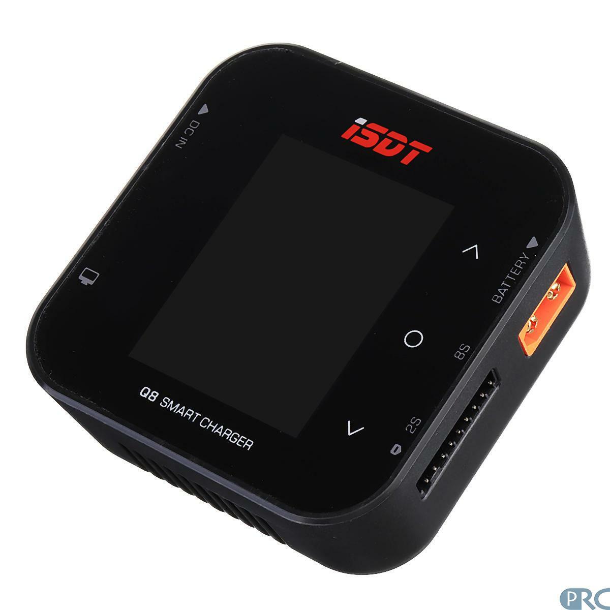
I did not feel the need to get the 100$ ISDT T8 (42V/30A input max.) but baught the 60$ ISDT Q8 charger instead, which is limited to 34V/20A input power.
However, a DC power supply for this Lipo battery charger ISDT Q8 can not be found at a reasonnable price.
As listed below in the specs, the charger can only take a maximum of 34V. It is pretty hard to find a power supply with high power and less than 34V AND more than 30V.
ISDT Q8 Specifications: www.isdt.co
Charging Power: DC 500W
Charging Current: 0.1A-20.0A
Discharging Power: 15W
Discharging Current: 0.1A-1.5A
Input Voltage: DC 10-34V
Ouput Voltage: DC 1-34V
Support Battery:
LiFe,Lion,LiPo 1-8S
LiHV:1-7S
Pb: 1-12S
NiMH: 1-16S
i found this beast DC power supply for LED strips on ebay:
1000W AC 110V-240V To DC 36/48V LED Power Supply Driver Adapter With Switch
However again, the voltage of this power supply can only be adjusted in a limited range of 38 - 34.1V, which is likely to fry the ISDT Q8 charger (i chickened out and did not try).
Also, there is a safety issue on mine, i did not really understand where it comes from, the ground is not well isolated and triggers the GFCI safety fuse... 8 volts AC on the ground pin. i will have this mounted in a wooden or plastic box just in case!
The power supply is opened with 2 screws to change the AC power input, and the board can be easily removed from the box after carefully removing a few other screws hidden behind the sticker (this voids warranty - btw what warranty? on ebay, it costs 60$ : 16$ of power supply and the rest of express shipping from china, or if you got it on amazon : 16$ of board and the rest of profit for amazon).
The variablre resistor aside the green led light is connected to a 3.9 kOhm 1/4W resistor. the latter is the voltage range limiter. i replaced it with a 4.7 kOhm 1/4W resistor to obtain a voltage range of 36.0 - 30.1V ~27Amperes.
i chose to adjust the voltage to 33.0V to prevent temperature voltage drifts to go outside specifications, noxious for the charger...
this is a pretty easy modification and charger works at full power (550W)
This page is describing the construction of an Arduino-based electric device and program i created. I could not find a proper/cheap solution that fitted my needs to remotely control speed and direction of a G-scale train pulling my 10 month old on a homemade G-scale flat car (picture below).
It is perfect too for any type of mobile control of a DC train outside or inside (range +/-100m).
The flat car with dolls enjoying the ride.
This is based on special ball bearings mounted wheels and homemade steel trucks to accomodate the always heavier baby. Note the truck-car attachment s also made with ball bearings to limit side wiggeling.
- Pcb board with holes ready to solder
- Female plugs : 2.54mm single row female pitch header socket connector (ebay) (for arduino nano on pcb)
- 2 position switch for invertion of track power (manual toggle, the software also inverts it!)
Electronics:
- Arduino nano (or uno or mega)(ebay)
- Md10c (Cytron 13A, 5-30V Single DC Motor Controller) (14$ ebay)
- Bluetooth Modem - BlueSMiRF Silver (silver or gold) (25$ amazon or ebay)
- 5vdc regulator 7805 (ebay) + heat sink (or piece of metal and a screw)
Arduino Nano and Bluesmirf power board: Note: the only PMW compatible pins of the arduino nano are the following 3, 5, 6, 9, 10, 11. If changes are done to the pin output, make sure you use those pins for PMW.
This PCB board connects 3 modules : the arduino nano, the Sparkfun Bluesmirf modules and the DC motor controller module MD10C
This board can also be used to configure the Bluesmirf with the arduino using the program present on the sparkfun link above (the Tx and RX ports common to the USB ports are not used here).
---------------------------
3- The program
Beta version of the arduino program is below.
A version with inertial support is not yet ready. Make the below text " .ino" and load it in Arduino IDE program.
Arduino program v0.4 (speed+ direction only):
<99 br="" cmdindex="">/***************************************************************************** //created by Maxime G. Cuypers on 23-fev-2018 for Jamie s train control by bluetooth with roboremo //adaptated from rc car control sketch for direction control //adaptated from MD10c sketches to control pmw //bluetooth module Bluesmirf gold * AUTHOR : Maxime Cuypers * COMPANY : private * REVISION : 0.4 * DATE : 26/04/2021 ********************************************************************************/ //v0.4 has inertial acceleration and deceleration, full smooth automatic reverse, emergency stop.
#include <SoftwareSerial.h>
/******************************************************************************* * IO DEFINITION * *******************************************************************************/ //setup bluetooth bluesmirf port int bluetoothTx = 2; // TX-O pin of BT module to Arduino pin2 int bluetoothRx = 3; // RX-I pin of B module to Arduino pin3
//const = variable "read-only". const int pinPwm = 5; // PWM is connected to pin 5. const int dirPin = 6; //direction signal connected to pin 6. /******************************************************************************* * PRIVATE GLOBAL VARIABLES * *******************************************************************************/
int val = 0; //Desired speed value int vitesse = 0; //Actual speed train runs int accel = 150; // Speed to accelerate, lower numbers are faster int decel = 60; //Speed to decelerate, lower numbers are faster int accraw = 150; // Speed to accelerate, lower numbers are faster int decraw = 60; //Speed to decelerate, lower numbers are faster int inversion = false; // inversion in progress = true int valapresinv = 0;
static unsigned long lastAccelTime = 0; //declared static so that it stores values in between function calls, but no other functions can change its value static unsigned long lastDecelTime = 0;
void setup() { // at power on delay(500); // wait for bluetooth module to start pinMode(dirPin, OUTPUT); digitalWrite(dirPin, LOW); //Low to high status changes direction // pinMode(forwardPin, OUTPUT); // digitalWrite(forwardPin, LOW); // pinMode(backwardPin, OUTPUT); // digitalWrite(backwardPin, LOW); // Initialize the PWM and DIR pins as digital outputs.(upon reset) pinMode(pinPwm, OUTPUT); // pinMode(pinDir, OUTPUT); // change Bluetooth module baud rate to 9600: bluetooth.begin(115200); // Bluetooth default baud is 115200 bluetooth.print("$"); bluetooth.print("$"); bluetooth.print("$"); // enter cmd mode delay(250); bluetooth.println("U,9600,N"); // change baud to 9600 bluetooth.begin(9600); cmdIndex = 0; }
void exeCmd() { if( cmd[0]=='f') { if (vitesse == 0 ) { digitalWrite(dirPin, !digitalRead(6)); // toggle direction on pin 6 if full stop } if( vitesse > 0 ) { // if train moving inversion = true; valapresinv = val; // store in memory to resume speed after inversion val = 0; //start deceleration } } if( cmd[0]=='v' && cmd[1]=='i' && cmd[2]=='t' && cmd[3]=='e' && cmd[4]=='s' && cmd[5]=='s' && cmd[6]=='e' && cmd[7]==' ') { String cmdStr; String valueStr; cmdStr = String(cmd); valueStr = cmdStr.substring(8); val = valueStr.toInt(); // target speed value 0-255 from bluetooth inversion = false; } if( cmd[0]=='r') { // r for reglage String cmdStr; String valueStr; cmdStr = String(cmd); valueStr = cmdStr.substring(1); accraw = valueStr.toInt(); // target inertal acceleration value 0-9 from bluetooth accel = 20 * accraw; decel = 20 * accraw; } if( cmd[0]=='a') { // stop - arret analogWrite(pinPwm, 0); //emergency stop val = 0; vitesse = 0; } }
void loop() { if(bluetooth.available()) { char c = (char)bluetooth.read(); cmd[cmdIndex] = c; if(cmdIndex<99) cmdIndex++; if(c=='\n') { // each command ends with '\n' exeCmd(); cmdIndex = 0; } } unsigned long currentTime = millis(); // ****Acceleration**** if (currentTime - lastAccelTime > accel) { lastAccelTime = currentTime; if (vitesse < val) { vitesse++; analogWrite(pinPwm, vitesse); } } // ****Deceleration**** if (currentTime - lastDecelTime > decel) { lastDecelTime = currentTime; if (vitesse > val) { vitesse = vitesse / 1.01; analogWrite(pinPwm, vitesse); } } //inertial invertion upon reverse request in "void exeCmd" if ((inversion == true) && (vitesse == 0)) { //when deceleration completes... digitalWrite(dirPin, !digitalRead(6)); // toggle direction on pin 6 after full deceleration before resuming reverse speed val = valapresinv; //resume previous speed inversion = false; //reset inversion & continue acceleration } }